Différences entre les versions de « VOR-009 »
| (8 versions intermédiaires par 2 utilisateurs non affichées) | |||
| Ligne 1 : | Ligne 1 : | ||
{{Projet}} | |||
{{Brouillon}} | |||
== Description == | |||
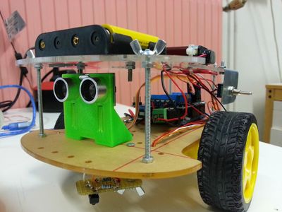
Vor09 est un petit robot à trois roues. | |||
Deux sont motorisées et la troisième est une roule libre. | |||
Ici le but est de faire une plate-forme roulante, pouvant servir pour d'autre projets. | |||
Le kit plaque + 2 moteur + 2 roues+ support de piles n'a couté que 8€. | |||
Rajouté 15 - 20€ pour l'arduino et le shield, 3€ de capteur et nous avons un robot fabriqué en Chine puis assemblé et programmé en France pour une trentaine d'euros ! | |||
[[Fichier:20141004_222428.jpg|400px]] | |||
Il embarque un arduino uno et un motorshield v2. | |||
Pour l'environnement nous avons un HC-SR04 pour éviter les obstacles, et un capteur infrarouge pour vérifier que l'on ne tombe pas. | |||
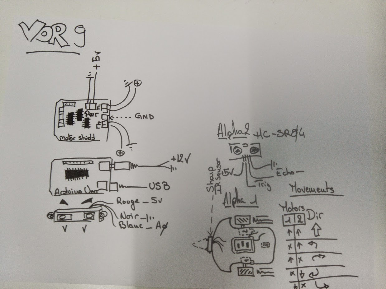
Si dessous les informations de montages, schema qui m'ont servi à le monter. | |||
[[Fichier:IMG_20140907_004901.jpg]] | |||
Schéma récapitulatif des branchements, avec la double alimentation. | |||
La première version de Vor09, devait avoir un capteur infrarouge Sharp, mais j'ai eu trop de difficulté à l'utiliser correctement, donc je me suis repliés sur une solution maîtrisée, le sonar. | |||
Noter le tableau pour gérer le pont en H. | |||
[[Fichier:20141008_002137.jpg|500px]] | |||
<table width="600"> | |||
<tr> | |||
<td colspan="6" width="600"><strong>VOR 09 - Arduino Uno + MotorShield Adafruit</strong></td> | |||
</tr> | |||
<tr> | |||
<td></td> | |||
<td></td> | |||
<td></td> | |||
<td></td> | |||
<td></td> | |||
<td></td> | |||
</tr> | |||
<tr> | |||
<td></td> | |||
<td></td> | |||
<td></td> | |||
<td></td> | |||
<td></td> | |||
<td></td> | |||
</tr> | |||
<tr> | |||
<td colspan="3"><strong>Motor Shield Mapping</strong></td> | |||
<td></td> | |||
<td></td> | |||
<td></td> | |||
</tr> | |||
<tr> | |||
<td></td> | |||
<td></td> | |||
<td></td> | |||
<td></td> | |||
<td></td> | |||
<td></td> | |||
</tr> | |||
<tr> | |||
<td></td> | |||
<td><strong>Motor Shield Pin</strong></td> | |||
<td><strong>Variable Name</strong></td> | |||
<td><strong>Feature</strong></td> | |||
<td><strong>Note</strong></td> | |||
<td></td> | |||
</tr> | |||
<tr> | |||
<td></td> | |||
<td>M1</td> | |||
<td>motorLeft</td> | |||
<td></td> | |||
<td>Motor 1</td> | |||
<td></td> | |||
</tr> | |||
<tr> | |||
<td></td> | |||
<td>M2</td> | |||
<td>motorRight</td> | |||
<td></td> | |||
<td>Motor 2</td> | |||
<td></td> | |||
</tr> | |||
<tr> | |||
<td></td> | |||
<td>M3</td> | |||
<td></td> | |||
<td></td> | |||
<td></td> | |||
<td></td> | |||
</tr> | |||
<tr> | |||
<td></td> | |||
<td>M4</td> | |||
<td></td> | |||
<td></td> | |||
<td></td> | |||
<td></td> | |||
</tr> | |||
<tr> | |||
<td></td> | |||
<td>A0</td> | |||
<td><strong>groundDetector</strong></td> | |||
<td><strong>Detection du sol</strong></td> | |||
<td></td> | |||
<td></td> | |||
</tr> | |||
<tr> | |||
<td></td> | |||
<td>A1</td> | |||
<td>sonarTrig</td> | |||
<td></td> | |||
<td></td> | |||
<td></td> | |||
</tr> | |||
<tr> | |||
<td></td> | |||
<td>A2</td> | |||
<td>sonarEcho</td> | |||
<td></td> | |||
<td></td> | |||
<td></td> | |||
</tr> | |||
<tr> | |||
<td></td> | |||
<td></td> | |||
<td></td> | |||
<td></td> | |||
<td></td> | |||
<td></td> | |||
</tr> | |||
<tr> | |||
<td></td> | |||
<td></td> | |||
<td></td> | |||
<td></td> | |||
<td></td> | |||
<td></td> | |||
</tr> | |||
<tr> | |||
<td colspan="3"><strong>Modules Mapping</strong></td> | |||
<td></td> | |||
<td></td> | |||
<td></td> | |||
</tr> | |||
<tr> | |||
<td></td> | |||
<td></td> | |||
<td></td> | |||
<td></td> | |||
<td></td> | |||
<td></td> | |||
</tr> | |||
<tr> | |||
<td></td> | |||
<td><strong>TCRT5000 Module</strong></td> | |||
<td><strong>Couleur du Cable</strong></td> | |||
<td><strong>Arduino Pin</strong></td> | |||
<td></td> | |||
<td></td> | |||
</tr> | |||
<tr> | |||
<td></td> | |||
<td>VCC</td> | |||
<td>Rouge</td> | |||
<td>5V</td> | |||
<td></td> | |||
<td></td> | |||
</tr> | |||
<tr> | |||
<td></td> | |||
<td>GND</td> | |||
<td>Blanc</td> | |||
<td>GND</td> | |||
<td></td> | |||
<td></td> | |||
</tr> | |||
<tr> | |||
<td></td> | |||
<td>Analog Input</td> | |||
<td>Orange</td> | |||
<td>A0</td> | |||
<td></td> | |||
<td></td> | |||
</tr> | |||
<tr> | |||
<td></td> | |||
<td></td> | |||
<td></td> | |||
<td></td> | |||
<td></td> | |||
<td></td> | |||
</tr> | |||
<tr> | |||
<td></td> | |||
<td></td> | |||
<td></td> | |||
<td></td> | |||
<td></td> | |||
<td></td> | |||
</tr> | |||
<tr> | |||
<td></td> | |||
<td><strong>HC-SR04 Module</strong></td> | |||
<td><strong>Couleur du Cable</strong></td> | |||
<td><strong>Arduino Pin</strong></td> | |||
<td></td> | |||
<td></td> | |||
</tr> | |||
<tr> | |||
<td></td> | |||
<td>GND</td> | |||
<td>Marron</td> | |||
<td>GND</td> | |||
<td></td> | |||
<td></td> | |||
</tr> | |||
<tr> | |||
<td></td> | |||
<td>Output</td> | |||
<td>Rouge</td> | |||
<td>A2</td> | |||
<td></td> | |||
<td></td> | |||
</tr> | |||
<tr> | |||
<td></td> | |||
<td>Trigger Input</td> | |||
<td>Orange</td> | |||
<td>A1</td> | |||
<td></td> | |||
<td></td> | |||
</tr> | |||
<tr> | |||
<td></td> | |||
<td>VCC</td> | |||
<td>Jaune</td> | |||
<td>5V</td> | |||
<td></td> | |||
<td></td> | |||
</tr> | |||
</table> | |||
== VOR-009 sur notre blog == | |||
Un robot suiveur de ligne servant également de plate-forme de test pour l'odométrie (inspiré du robot Zumo de Pololu). | |||
Ce projet n'est pas encore documenté mais plusieurs billets en parlent sur notre blog : | Ce projet n'est pas encore documenté mais plusieurs billets en parlent sur notre blog : | ||
| Ligne 9 : | Ligne 262 : | ||
* [http://www.vorobotics.com/wp/des-nouvelles-de-vor09-et-du-lab/ 21 novembre 2014] | * [http://www.vorobotics.com/wp/des-nouvelles-de-vor09-et-du-lab/ 21 novembre 2014] | ||
* [http://www.vorobotics.com/wp/vor09-le-premier-robot-fonctionnel-du-lab/ 27 août 2014] | * [http://www.vorobotics.com/wp/vor09-le-premier-robot-fonctionnel-du-lab/ 27 août 2014] | ||
Version actuelle datée du 25 juillet 2016 à 14:18
← Accueil ← Nos Projets
Description
Vor09 est un petit robot à trois roues. Deux sont motorisées et la troisième est une roule libre.
Ici le but est de faire une plate-forme roulante, pouvant servir pour d'autre projets. Le kit plaque + 2 moteur + 2 roues+ support de piles n'a couté que 8€. Rajouté 15 - 20€ pour l'arduino et le shield, 3€ de capteur et nous avons un robot fabriqué en Chine puis assemblé et programmé en France pour une trentaine d'euros !
Il embarque un arduino uno et un motorshield v2.
Pour l'environnement nous avons un HC-SR04 pour éviter les obstacles, et un capteur infrarouge pour vérifier que l'on ne tombe pas.
Si dessous les informations de montages, schema qui m'ont servi à le monter.
Schéma récapitulatif des branchements, avec la double alimentation.
La première version de Vor09, devait avoir un capteur infrarouge Sharp, mais j'ai eu trop de difficulté à l'utiliser correctement, donc je me suis repliés sur une solution maîtrisée, le sonar.
Noter le tableau pour gérer le pont en H.
| VOR 09 - Arduino Uno + MotorShield Adafruit | |||||
| Motor Shield Mapping | |||||
| Motor Shield Pin | Variable Name | Feature | Note | ||
| M1 | motorLeft | Motor 1 | |||
| M2 | motorRight | Motor 2 | |||
| M3 | |||||
| M4 | |||||
| A0 | groundDetector | Detection du sol | |||
| A1 | sonarTrig | ||||
| A2 | sonarEcho | ||||
| Modules Mapping | |||||
| TCRT5000 Module | Couleur du Cable | Arduino Pin | |||
| VCC | Rouge | 5V | |||
| GND | Blanc | GND | |||
| Analog Input | Orange | A0 | |||
| HC-SR04 Module | Couleur du Cable | Arduino Pin | |||
| GND | Marron | GND | |||
| Output | Rouge | A2 | |||
| Trigger Input | Orange | A1 | |||
| VCC | Jaune | 5V | |||
VOR-009 sur notre blog
Un robot suiveur de ligne servant également de plate-forme de test pour l'odométrie (inspiré du robot Zumo de Pololu).
Ce projet n'est pas encore documenté mais plusieurs billets en parlent sur notre blog :


